Accelerometer with microcontroller and display
The accelerometer can measure acceleration in two axis using Analog Devices ADXL202. +-2g can be measured in each axis. Look here for datasheets and application notes.
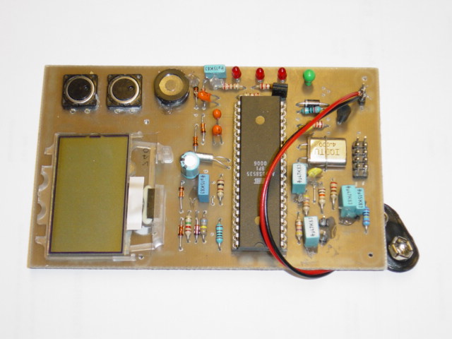
Accelerometer with microcontroller and display
CPU is an ATMEL AT90S8535 running at 4Mhz. A 32768 Hz crystal is connected to the real time clock timer inputs (TIMER2) and is the time base for the accelerometer. This allows a ceramic resonator to be used instead of a crystal if desired. A ceramic resonator should provide even lower power consumption. Power to all subcomponents like display and accelerometer senser are controlled by the CPU so that they can be turned off to save power.
The ADXL is connected to the Input Capture Pin (ICP) and the analog comparator. Rset of the ADXL that controls the period time is set so that there is approximatly 20000 ticks to one period.
The LCD display have 3 rows and is connected to the CPU using two data pins. The LCD uses I2C protocol and uses a variant of this driver circuit. A negative voltage charge pump is driven by the CPU to generate the bias voltage needed by the display. By measuring the bias voltage voltage with the ADC the CPU can regulate the negative voltage. A voltage divider between the negative lcd bias and the battery makes the voltage in a range to be measured.
Vref to the ADC is connected directly to the battery. One of the ADC inputs is connected to a reference voltage from a zener diode. The zener is driven by one of the pins from the CPU. This minimises the current consumption by just turning on the reference voltage when Vbatt need to be calculated from measurements of the zener voltage.
RS232 line driver. A simple transistor inverts the output from the Tx line so that it can be connected to an PC RS232 port. Two buttons are connected. Through two diodes they each can pull down INT1 to wake the CPU if necessary. Three LED provide debug status, TIMER2 ticks, Idle/PowerSave and On/Off. Audio feedback is provided through a small buzzer. Each hardware is wrapped by a macro in the hardware.h file. No port is accessed directly without using a macro.
 PD7 [out] BLUE LED (1s alive blink)
 PD6 [in]  ICP; ADXL x-axis (8535:pin20)
 PD5
 PD4 [out] BUZZER_OUT
 PD3 [in]  INT1. _WAKEUP  (8535:pin17)
 PD2       INT0.  (8535:pin16)
 PD1 [out] UART TXD (8535:pin15)
 PD0 [in]  UART RXD (8535:pin14)

 PC7 [in]  32678 Hz Crystal
 PC6 [out] 32678 Hz Crystal
 PC5 [i/o] I2C Data (8535:pin27)
 PC4 [i/o] I2C Clk (8535:pin26)
 PC3 [out] LCD_PWR  (8535:pin25)
 PC2 [out] LCD_CHARGE_PUMP2  (8535:pin24)
 PC1 [out] LCD_CHARGE_PUMP1  (8535:pin23)
 PC0 [out] LCD_CHARGE_PUMP0  (8535:pin22)

 PB7 [in]  SCK   (8535:pin8)
 PB6 [out]  MISO   (8535:pin7)
 PB5 [in] MOSI   (8535:pin6)
 PB4       _SS
 PB3 [in]  AIN1;(ADXL Power / 2) (8535:pin4)
 PB2 [in]  AIN0; ADXL y-axis (8535:pin3)
 PB1 [out] ADXL Power (8535:pin2)
 PB0 [out] RED LED (on if CPU clock is on, off is CPU is in power save)

 PA7
 PA6   (8535:pin34)
 PA5
 PA4
 PA3
 PA2 [out] Vref supply  (8535:pin38)
 PA1 [ain] VLCD Meas    (8535:pin39)
 PA0 [ain] Vcc measure  (8535:pin40)
//ADXL TIMER1 interrupts begin
INTERRUPT(SIG_INPUT_CAPTURE1)
{
  //Get the captured counter
  uint16_t cnt = TIMER1_READ_INPUT_CAPTURE();

  //Normalize to ticks after TaTc, use the fact that it is
  //16 bit timer and 16bit arithmetics is used
  cnt -= TaTc;

  //Check prescaler, if cnt < 65536 / 4 then we can use a lower
  //prescaler value
  #if (ADXL_AUTOMATIC_PRESCALER_ENABLED == 1)
  if (!Timer1_Prescaler_Decrease(cnt))
  #endif //(ADXL_AUTOMATIC_PRESCALER_ENABLED == 1)
  {
    if (validMeasurements > 0)
    {
      validMeasurements--;
    }
    else
    {
        if (AxisX > CalibrationMeasured.TxMax)
          CalibrationMeasured.TxMax = AxisX;
        if (AxisX < CalibrationMeasured.TxMin)
          CalibrationMeasured.TxMin = AxisX;
        if (AxisY > CalibrationMeasured.TyMax)
          CalibrationMeasured.TyMax = AxisY;
        if (AxisY < CalibrationMeasured.TyMin)
          CalibrationMeasured.TyMin = AxisY;
    }

    //See algorithm description in .h file.
    if (TIMER1_INPUT_CAPTURE_IS_RISING_EDGE())
    {
      //(a) (c)
      TaTc += cnt;

      CalibrationMeasured.Tp =
        FIR_Filter_BoxCar_Input(&periodFilter.filter, (FIR_FilterSample_t)cnt);

      //Enable overflow detection
      TIMER1_SET_OUTPUT_COMPARE_A(TaTc + ADXL_TIMERTICKS_OVERRUN);
      TIMER1_INPUT_CAPTURE_FALLING_EDGE();
    }
    else {
      // (b) (d)
      if (ADXL_IS_X_AXIS())
      {
        //(b)
        AxisX = FIR_Filter_BoxCar_Input(&AxisXFilter.filter, (FIR_FilterSample_t)cnt);

        ADXL_SELECT_Y_AXIS();
      }
      else {
        // (d)
        AxisY = FIR_Filter_BoxCar_Input(&AxisYFilter.filter, (FIR_FilterSample_t)cnt);

        ADXL_SELECT_X_AXIS();
      }
      TIMER1_INPUT_CAPTURE_RISING_EDGE();
    }
  }
}


INTERRUPT(SIG_OUTPUT_COMPARE1A)
{
  //Timer 1 overflowed, increase prescaler and reset the number of valid validMeasurements
  //uS_counter = 0;

#if (ADXL_AUTOMATIC_PRESCALER_ENABLED == 1)
  Timer1_Prescaler_Increase();
#endif //(ADXL_AUTOMATIC_PRESCALER_ENABLED == 1)
  RED_LED_CHANGE();

  validMeasurements = ADXL_STABLE_MEASUREMENT_COUNT;
}


//ADXL TIMER1 interrupts end
//TIMER2 Interrupts begin

INTERRUPT(SIG_OUTPUT_COMPARE2)
{
  Timers_Update();
}

INTERRUPT(SIG_OVERFLOW2)
{
  //TIMER2_DEBUG_OUTPUT_CHANGE();
  //DEBUG_PRINT_INFO_(".");
  RTC_Increase(TIMER2_RTC_UPDATE_TIME);
}

//TIMER2 Interrupts end
  //Main program loop begin
  FOREVER
  {
    static bool ButtonPressed = false;

    //Update the LCD charge pump timer
    UpdateLCDChargePumpTimer();

    if (ButtonPressed)
    {
      if (!BUTTON_RESET_DOWN() && !BUTTON_MODE_DOWN())
      {
        ButtonPressed = false;
      }
    }
    else {
      if (BUTTON_MODE_DOWN())
      {
        AccelR8_Mode_t mode = currentMode;

        ButtonPressed = true;

        Buzzer_Buzz();

        mode++;
        if (mode >= AccelR8_Mode_LAST) mode = AccelR8_Mode_FIRST;

        Timer_Set(TIMER_SWITCH_OFF,TIMER_SWITCH_OFF_ON_TIMEOUT);

        Mode_NewMode(mode);
      }

      if (BUTTON_RESET_DOWN())
      {
        ButtonPressed = true;

        Buzzer_Buzz();

        switch (currentMode)
        {
          case AccelR8_Mode_Calibrate:
            {
              const ADXL_CalibrationInfo_t* info_p =
                ADXL_GetMeasuredCalibrationInfo();

              eeprom_write_block(info_p,(void*)&EEPROM_SavedCalibrationData,sizeof(ADXL_CalibrationInfo_t));
            }
            break;
          case AccelR8_Mode_LateralAcceleration:
            z_offset = current_acceleration;
            horiz_speed = 0;
            break;

          default:
            break;

        }
      }
    }

    //Update display
    if (Timer_HasExpired(TIMER_UPDATE_DISPLAY))
    {
      UpdateDisplay();
    }

    if (Timer_HasExpired(TIMER_SWITCH_OFF))
    {
      Mode_NewMode(AccelR8_Mode_Off);
    }

    if (Timer_HasExpired(TIMER_LOG))
    {
      ADXL_g_t axisX = ADXL_GetX();
      ADXL_g_t axisY = ADXL_GetY();

      axisX/=10;
      axisY/=10;

      uart_printf("%+05d %+05d\r", axisX, axisY);
    }

    //Read ADC
    if (Timer_HasExpired(TIMER_READ_ADC))
    {
      dbg_printf("\r\nVlcd:%6dmV tmr:%6dms", LCD_Voltage_Current, LCD_ChargePumpTimer);

      ADC_ReadValue = 0xFFFF;
      CPU_Clock_Allocate();
      ADC_ENABLE();
      ADC_SETUP_MUX(ADC_MUX_VLCD);
      ADC_ENABLE_INTERRUPT();
      ADC_START();
    }

    //LCD Charge Pump
    if (Timer_HasExpired(TIMER_LCD_CHARGE_PUMP))
    {
      LCD_CHARGE_PUMP_TOGGLE();
      Timer_Set(TIMER_LCD_CHARGE_PUMP,LCD_ChargePumpTimer);
    }

    //Wait 1s for 32KHz crystal to stabilize before going to powersave mode
    if (Timer_HasExpired(TIMER_TIMER2_STABILIZE))
    {
      Timer_Reset(TIMER_TIMER2_STABILIZE);
      DEBUG_PRINT_INFO_("\r\nTIMER2 stable...\r\n");
      CPU_Clock_Free();
    }

    //LED blink alive indication
    if (Timer_HasExpired(TIMER_BLUE_LED))
    {
      BLUE_LED_CHANGE();
    }

    //Check if any timer already expired
    if (Timers_GotoToIdle())
    {
      //Is clock needed by any resource?
      if (CPU_Clock_IsAllocated() || !Buzzer_PowerSaveOk())
      {
        //Yes. Only goto idle
        //CPU_IDLE();


        MCUCR |= _BV(SE);
        __asm__ __volatile__ ("sleep" "\n\t" :: );
        MCUCR &= ~_BV(SE);
     }
      else {
        //Nope, no clock needed. Powersave.
        RED_LED_OFF();
        UART_POWER_SAVE_SLEEP();
        ADC_DISABLE();
        CPU_POWER_SAVE();
        UART_POWER_SAVE_WAKEUP();
        RED_LED_ON();
      }
    }
  }
  //Main program loop end